CNC Mill
Computer numerical control (CNC) Milling is a form of milling where the
CNC Safety
A CNC Mill is a dangerous piece of industrial equipment and safety must be considered durring operation.
The dangers include
-
High Roataional Energy
A moderate risk in CNC Mill durring operations and setup.
This can casue lacerations.
This is generaly caused by contact with the tooling or overextending while removing material from the chuck.
To reduce the risk of harm, utilize a brush to move any material fro around the tool and do not use your hands. Additionaly when untightening the vice pull the lever twords your body and not away. -
Flying Debris
A minor risk in CNC Mill operations is being struck by debris.
This debris can be metal shavings, objects that have been parted off, or shattered tooling.
This can cause minor lacerations and eye injury.
To reduce the risk of harm, always wear saftey glasses while in proximity of an operational CNC Mill, and confirm the shield is in place. -
Sharp Edges
A minor risk in CNC Mill operations in being cut by sharp edges.
Objects like metal shavings, cutting surfaces, and machined edges have sharp edges.
This can cause minor lacerations.
To avoid being hurt do not handle metal shavings with bare hands, utilize cleaning tools and gloves.
To adoid being hurt machined parts should be sanded/filed to remove sharp edges.noteGloves should never be worn durring CNC Mill operation due to risk of entanglement.
CNC Mill Operation
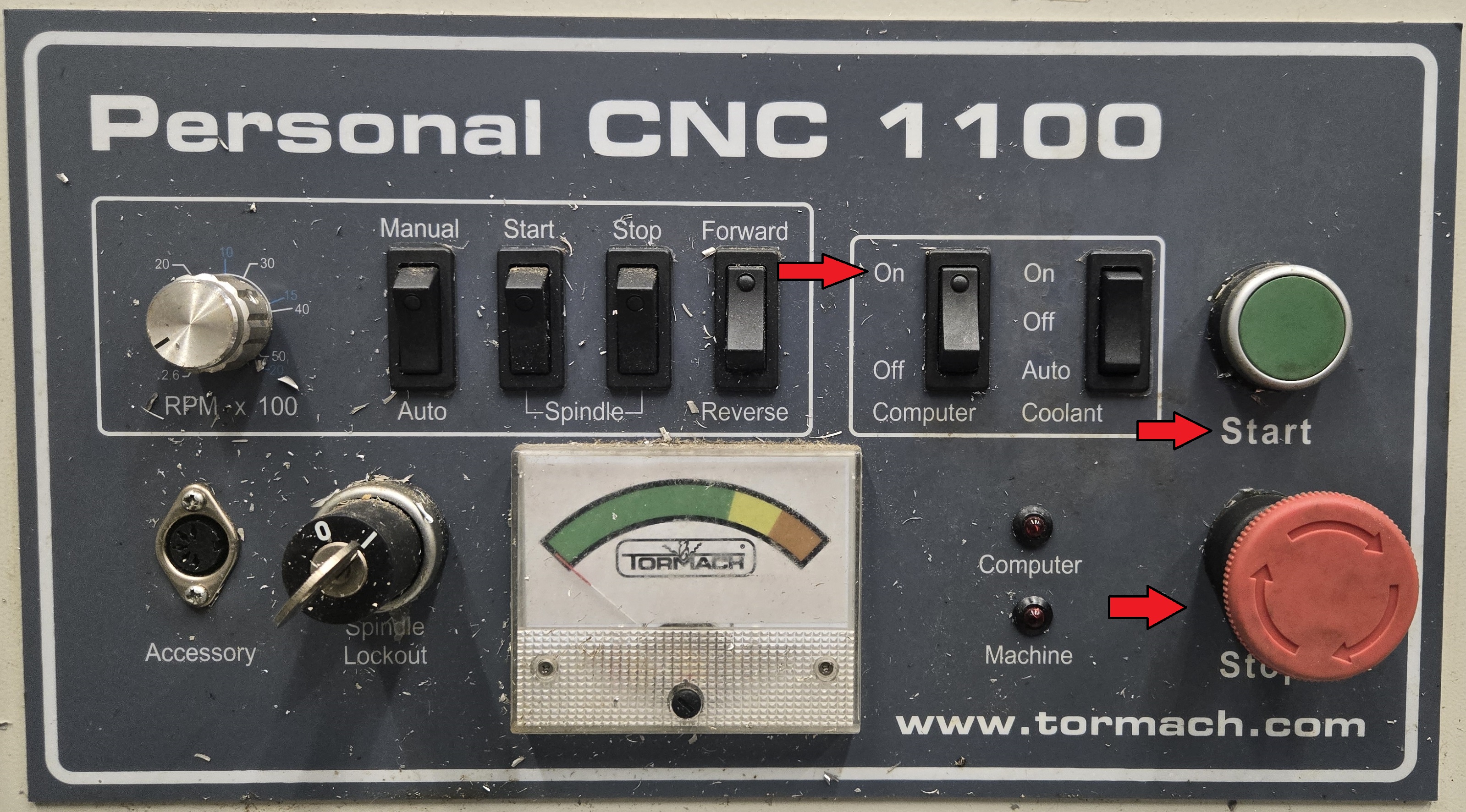
Machine Bootup
Initialize the machine.
- Computer switched to ON.
- Stop button un-depressed.
- Press Start button.
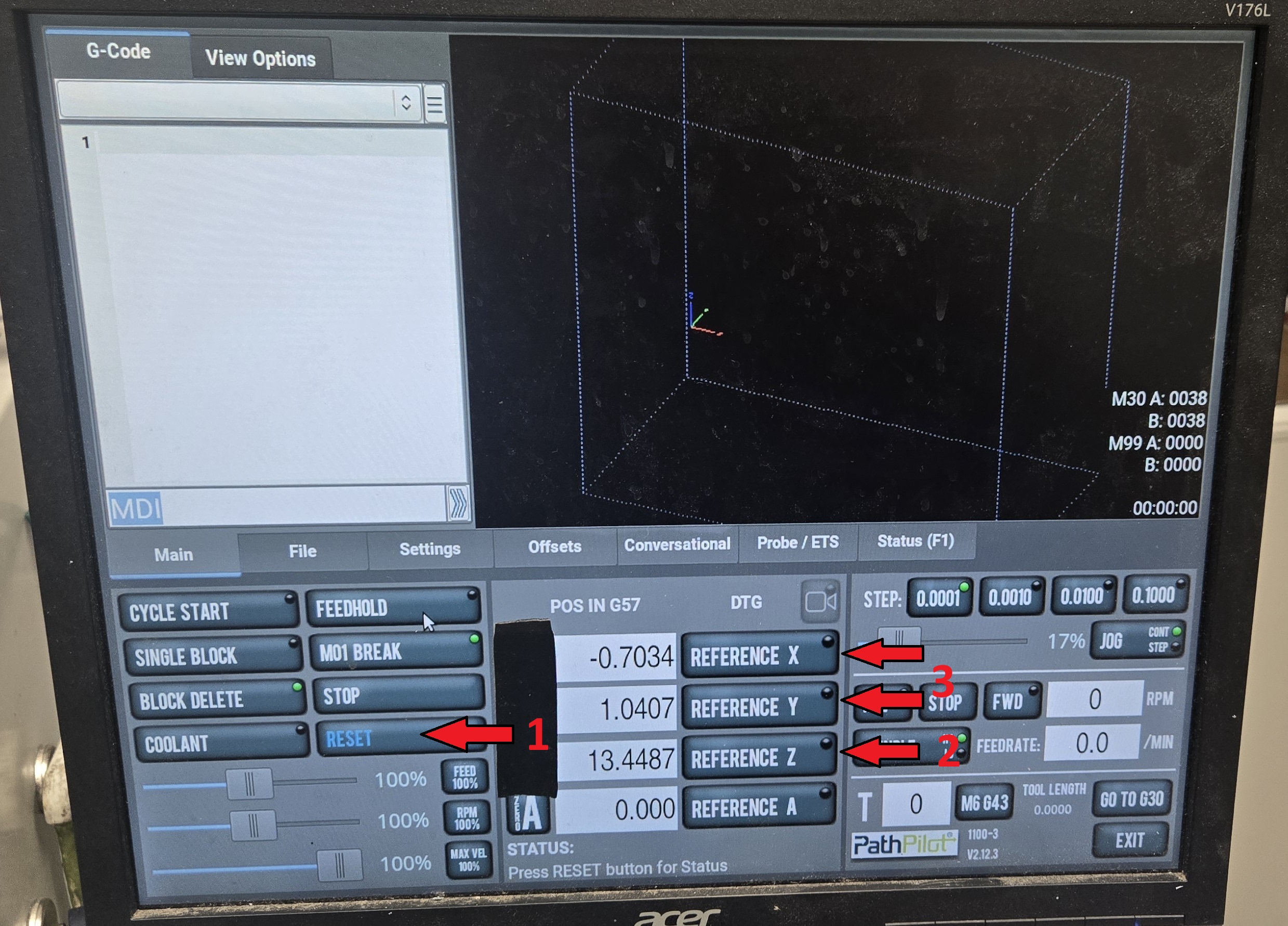
Reset the Axis.
- Press the blinking Reset button.
- Press Reference Z button and wait until motion stops.
- Press Reference X & Y buttons and wait until motion stops.
Program Setup
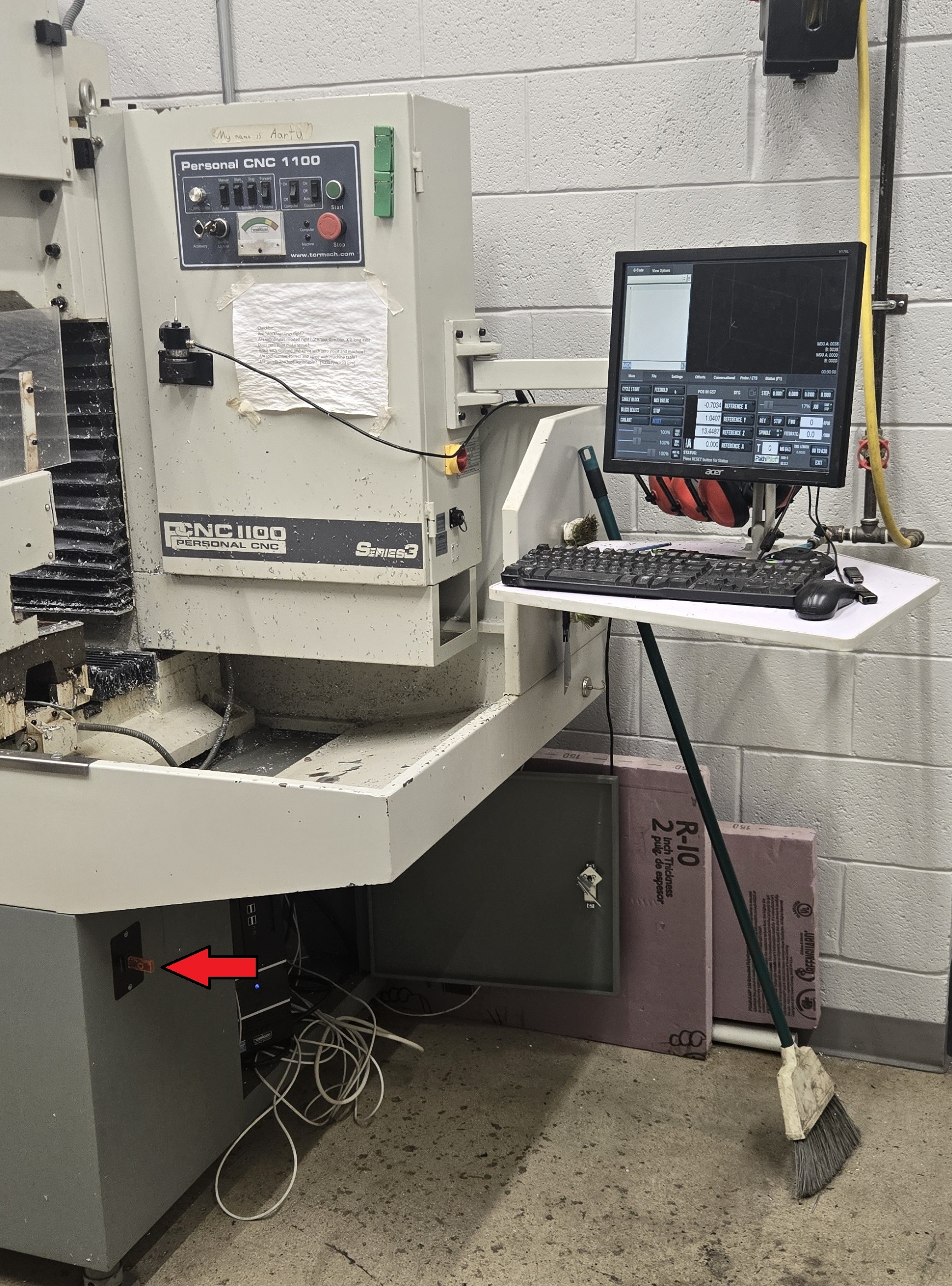
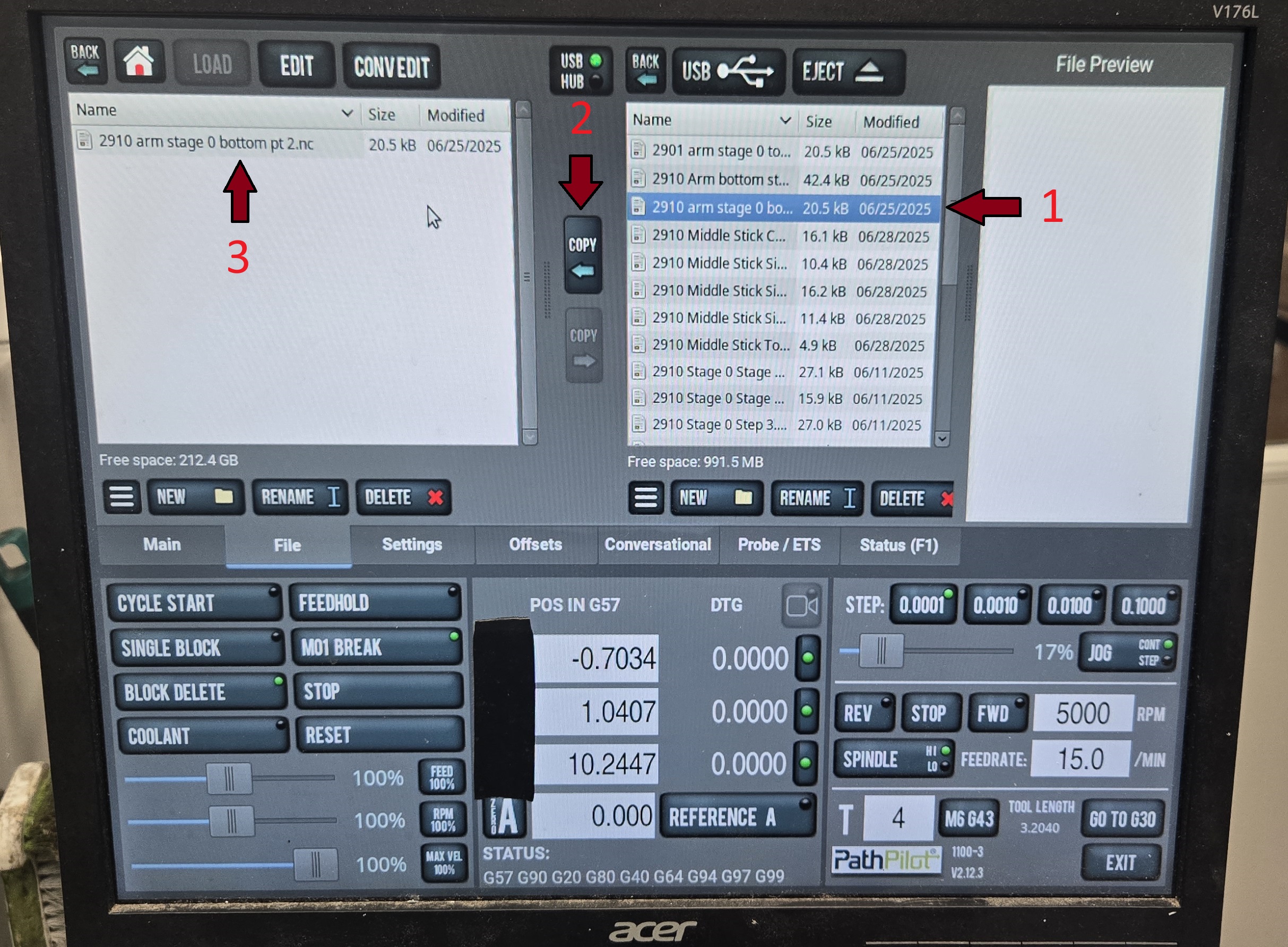
To begin CNC setup first you must import a file from a flash drive prepared by the fusion programmer.
- Insert the flash drive into the USB port located below the computer.
- Click on File.
- Navigate to the desired g-code file on the right side.
- Navigate to current years/projects g-code folder on the left side.
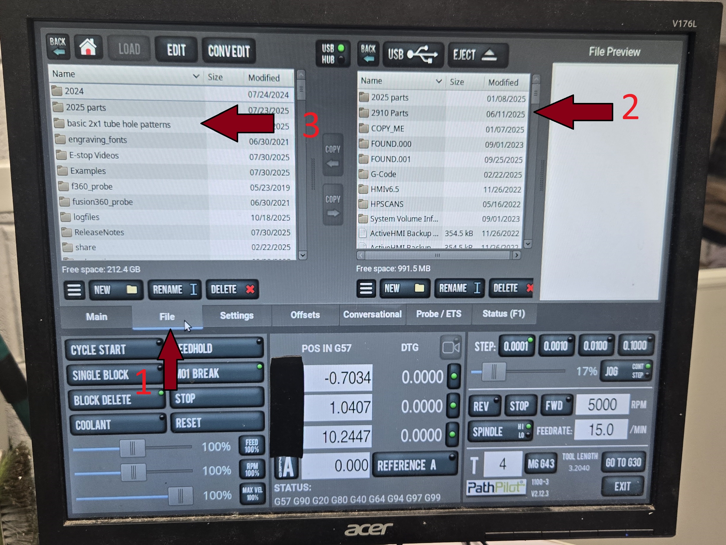
- Select desired file.
- Click Copy.
- Double click copied file.
Chucking Material
Confirm Setup
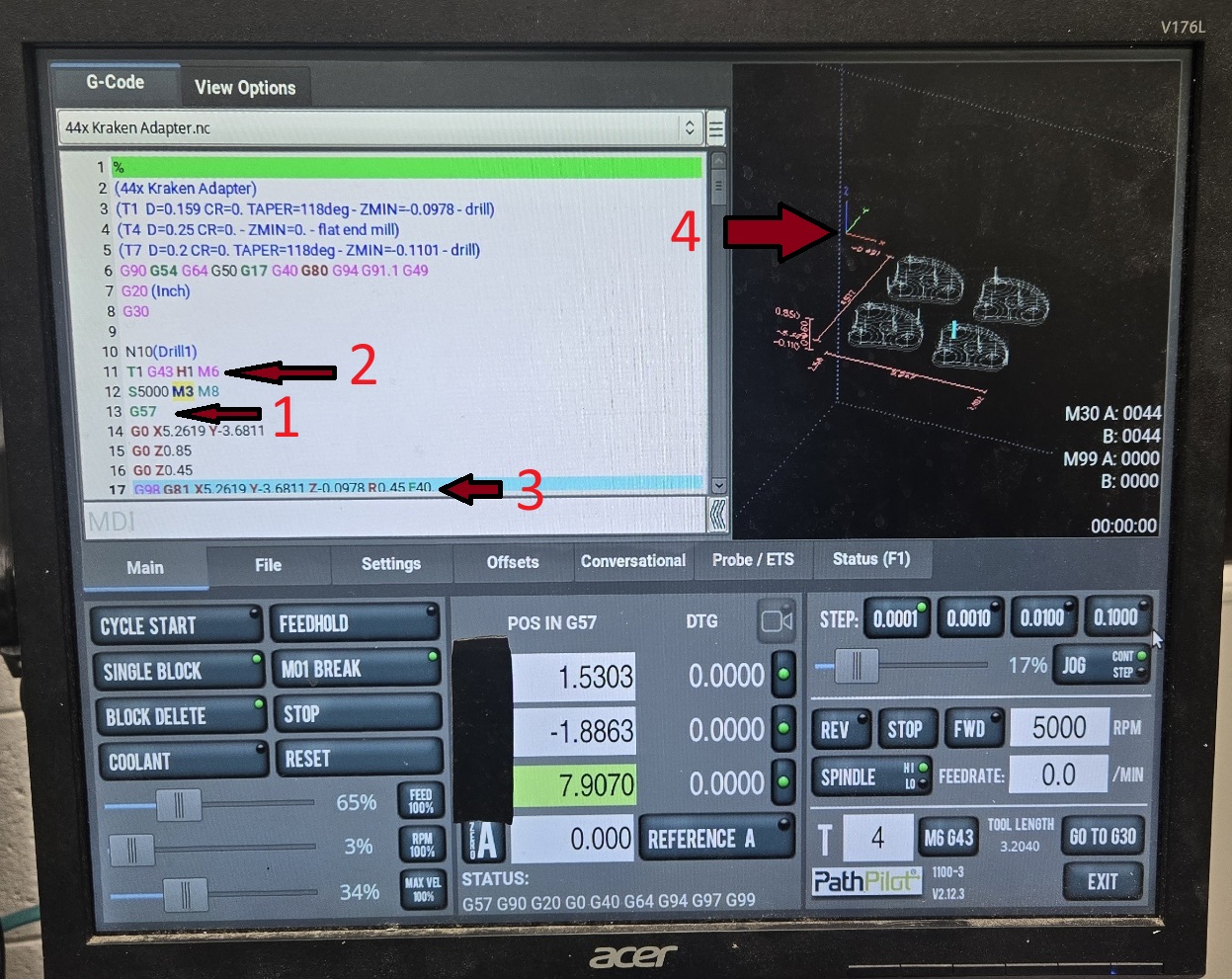
Once the program has been loaded and the material has been secured, it is important to check some key parts of the program.
- Confirm the correct work offset (G##).
- Find program work offset. (G54 - G59)
- Confirm chucked material orientation matches fusion setup and G-code graphic.
- Reference Tools & Offsets for what each work offset means.
- Most programs will use G57 as the work offset. Left side of the vice on top of the back parallels.
- Confirm the correct tool is loaded.
- Find program tool number. (T##)
- Confirm the tool number matches the tool loaded in the spindle.
- Reference Tools & Offsets for tool numbers.
- Confirm the correct spindle speed and feed rate.
- Find program feed rate. (F##)
- Confirm feed rate match the fusion recommended values for the loaded tool and material.
- Reference Tools & Offsets for feed rates.
- Visually inspect the toolpath.
- Use the G-code graphic to confirm the toolpath matches the intended design.
- Confirm the work offset location matches the chucked material.
- Confirm the tool does not collide with the vice, clamps, or any other obstructions
Run Program
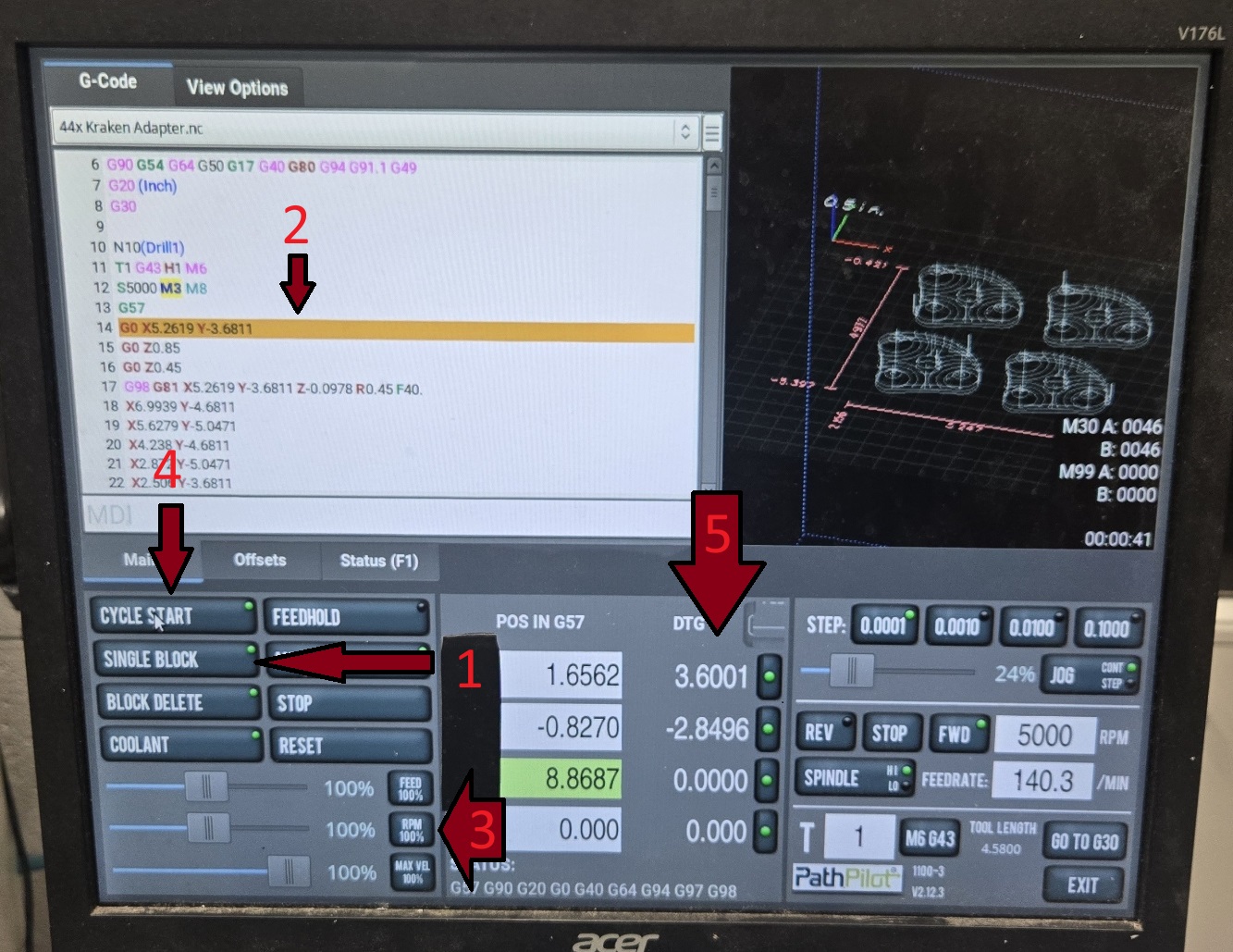
When all setup checks have been completed, the program is ready to run.
It is important to step through the start of the program and each machining operation to check for any issues.
- Turn on single block mode by pressing the Single Block button.
- The green light will turn on when single block mode is active.
- The yellow bar indicates the next line of code to be run.
- The speed of the mill should be limited during the initial setup validation.
- FEED refers to the cutting feed rate, and should be limited to 20-40% during validation.
- RPM refers to the spindle rotation speed, and should be set to 100% during validation.
- MAX VEL refers to the speed of the moments between cuts, and should be limited to 20-40% during validation.
- Press the Cycle Start button to run the next line of code.
- The numbers under the DTG (Distance To Go) indicate how far the tool has to travel in each axis to complete the current operation.
- Continuously step through the program and gauge wether it is moving to far to collide with any obstructions.
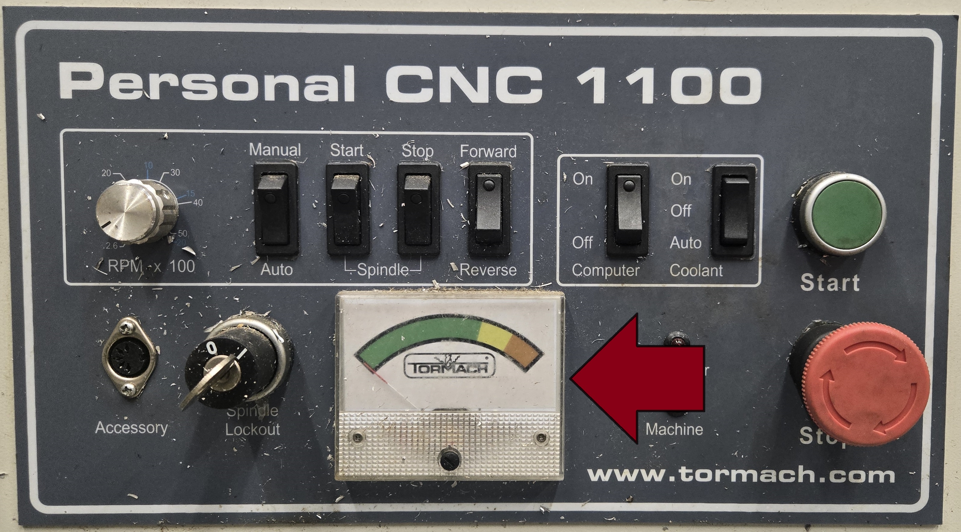
- While cutting and drilling, monitor the torque of the spindle motor.
- If the torque strays into the yellow zone reduce the feed rate.
- If the torque strays into the red zone, and feed rate reduction does not help, stop the program immediately and investigate the issue.
When the program step has been validated, single block mode can be turned off and the program can be run at full speed or reduced speed.
Once the program has reached a new operation, single block mode should be turned back on and the new operation should be validated before continuing.