Inertial Measurement Unit (IMU)
An Inertial Measurement Unit (IMU) is a critical sensor in FRC robotics that measures a robot's orientation, angular velocity, and linear acceleration. IMUs enable autonomous navigation, field-oriented drive systems, and precise robot positioning.
What is an IMU?
An IMU typically combines several sensors:
- Gyroscope: Measures angular velocity (rotation rate) around three axes
- Accelerometer: Measures linear acceleration along three axes
- Magnetometer: Measures magnetic field strength (compass functionality)
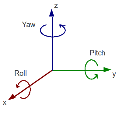
Together, these sensors provide 9 degrees of freedom (9-DOF) of motion data, allowing you to determine your robot's orientation in 3D space. The most important measurements are typically from the gyroscope (heading/yaw) and accelerometer (pitch and roll).
CTRE Pigeon 2.0
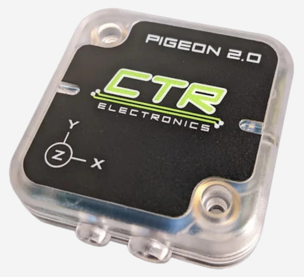
Key Features:
- 9-axis fusion algorithm for precise heading calculation
- CAN bus communication for reduced wiring
- Temperature compensation for improved accuracy
- Built-in vibration rejection
- Easy integration with Phoenix framework
Wiring:
CAN High (Yellow) → CAN Bus High
CAN Low (Green)   → CAN Bus Low
V+ (Red)          → 12V
GND (Black)       → Ground
CTRE Docs:
Kauai Labs (Studica Robotics) NavX-MXP
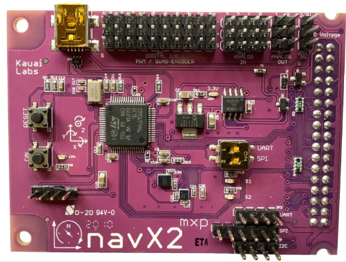
Key Features:
- 200Hz update rate for responsive control
- Multiple connection interfaces (SPI, I2C, USB, Serial)
- Built-in sensor fusion algorithms
- Collision detection capabilities
- Comprehensive software libraries
Wiring (SPI Connection - Recommended): Connect to the MXP port on the roboRIO:
MXP Pin 1  → 3.3V
MXP Pin 2  → DIO 0 (CS)
MXP Pin 4  → DIO 1 (MISO)
MXP Pin 6  → DIO 2 (MOSI)
MXP Pin 8  → DIO 3 (SCLK)
MXP Pin 14 → Ground
Studica Docs:
FRC Applications
1. Field-Oriented Drive
IMUs enable field-oriented (field-centric) drive systems where robot movement is relative to the field rather than the robot's orientation.
public void fieldOrientedDrive(double xSpeed, double ySpeed, double rotation) {
    // Get current robot heading
    double robotAngle = Math.toRadians(imu.getHeading());

    // Transform driver inputs to field-relative coordinates
    double fieldRelativeXSpeed = xSpeed * Math.cos(robotAngle) + ySpeed * Math.sin(robotAngle);
    double fieldRelativeYSpeed = -xSpeed * Math.sin(robotAngle) + ySpeed * Math.cos(robotAngle);

    // Drive the robot
    drivetrain.drive(fieldRelativeXSpeed, fieldRelativeYSpeed, rotation);
}
2. Autonomous Navigation
IMUs provide critical heading information for autonomous routines. Turning to a heading is a drivetrain state:
the state's updateLogic arm runs a PID on the yaw, and isAimed() lets the transition table (and the behavior
tree, through the robot's AIM state) know when it is done:
// In the drivetrain subsystem's constructor
turn_controller_ = new PIDController(0.02, 0, 0.004);
turn_controller_.setTolerance(2.0);              // 2 degree tolerance
turn_controller_.enableContinuousInput(-180, 180);

// updateLogic: the AIM arm commands the mechanisms, nothing else
case AIM -> {
    double turn = turn_controller_.calculate(getHeading(), target_angle_);
    drive_.arcadeDrive(0, turn);
}

// A condition the transition table and the robot's AIM state read
public boolean isAimed() {
    return turn_controller_.atSetpoint();
}
3. Balance Detection
Use IMU pitch readings to detect when your robot is on the charging station (2023):
public boolean isOnChargingStation() {
    double pitch = Math.abs(imu.getPitch());
    return pitch > 10.0; // Robot is tilted more than 10 degrees
}

public boolean isBalanced() {
    double pitch = Math.abs(imu.getPitch());
    return pitch < 2.5; // Robot is within 2.5 degrees of level
}
Troubleshooting
- IMU not detected: Check wiring and CAN/SPI connections
- Inconsistent readings: Ensure proper mounting and calibration
- Drift over time: Implement periodic resets and consider environmental factors
- Noisy data: Add software filtering or check for mechanical vibration